

Repeatable Test to Tune Battery Low Voltage Cutoff for RVs
Repeatable Test to Tune Battery Low Voltage Cutoff for RVs

A battery low voltage cutoff, or low-voltage disconnect (LVD), automatically drops non-critical loads before your bank falls into damaging deep discharge. For a practical starting point, set 12V LiFePO4 cutoffs around 11.8 to 12.2V and 12V lead-acid cutoffs closer to 11.8 to 12.0V, then adjust for your actual wiring and battery maker’s specs. Cold weather, cable sag, and battery age all shift the right number for your system.
TL;DR:
- Use 11.8 to 12.2V for 12V LiFePO4 cutoffs and 11.8 to 12.0V for lead-acid batteries, adjusting for weather, wiring, and manufacturer specs.
- Place the voltage sensor close to the battery terminals to prevent false low-voltage readings caused by cable resistance or load surges.
- Set alarm thresholds first for early warning and tune cutoff points after confirming the resting voltage to avoid excessive capacity loss or damage.
- Use a time delay of around 60 seconds and hysteresis of 0.4 to 0.8V to prevent nuisance trips during load fluctuations.
- Match the LVD device’s voltage range and adjustable features to your system’s chemistry, voltage, and load characteristics for optimal protection.
Table of Contents
- What Is a Low-Voltage Disconnect, and Why Do You Need One?
- Practical Cutoff and Alarm Voltage Ranges by System Voltage and Chemistry
- How Low-Voltage Cutoff Devices Work: Trip Logic, Delay, and Hysteresis
- How to Set and Tune Your LVD: A Repeatable Test Procedure
- Choosing the Right LVD Device for Your System
- Installation Checklist and Wiring Best Practices
- Testing and Troubleshooting Your LVD After Installation
- Field Perspective: What Actually Goes Wrong in Off-Grid Installs
- Western Harmonics: Hardware and Design Tools Built for This
- Sources
What Is a Low-Voltage Disconnect, and Why Do You Need One?
A low-voltage disconnect monitors battery voltage and cuts power to non-critical loads before the bank reaches a dangerously low state of charge, protecting cell health and holding back a reserve for things you actually need, like a fridge or a communication radio in an RV. That’s the whole job in one sentence, but the mechanics behind it matter if you want the device to actually help instead of annoy you.
Most systems use three thresholds working together. An alarm voltage warns you that the bank is getting low, but nothing disconnects yet. The cutoff voltage is where the LVD actually opens the circuit to non-critical loads. The restart voltage (sometimes called recovery voltage) is where the load reconnects once the battery has recovered from charging. Restart always sits meaningfully higher than cutoff, which prevents the device from clicking on and off repeatedly around one threshold.
Deep discharge damages batteries differently depending on chemistry. Lead-acid batteries suffer sulfation when repeatedly drawn too low. The lead sulfate crystals harden on the plates and permanently reduce capacity. LiFePO4 cells tolerate deeper discharge far better, but pushing individual cells below their safe floor still degrades the cathode material and can trigger a battery management system (BMS) to lock out the pack entirely, sometimes requiring a manual reset.
An LVD works alongside, not instead of, other protection layers:
- A standalone LVD is often the primary protection layer in systems without a smart lithium BMS, such as older lead-acid setups.
- On lithium banks, the internal BMS handles hard cell protection, and the LVD or inverter cutoff should trip earlier, so the BMS disconnect is a backstop, not the first line of defense.
- Inverters with a built-in low-voltage cutoff (LVC) add a second checkpoint, especially useful for AC loads that draw heavily and pull voltage down fast.
The goal across all three layers is the same: catch the low-voltage event early enough that you never actually need the BMS to slam the door shut.
Practical Cutoff and Alarm Voltage Ranges by System Voltage and Chemistry
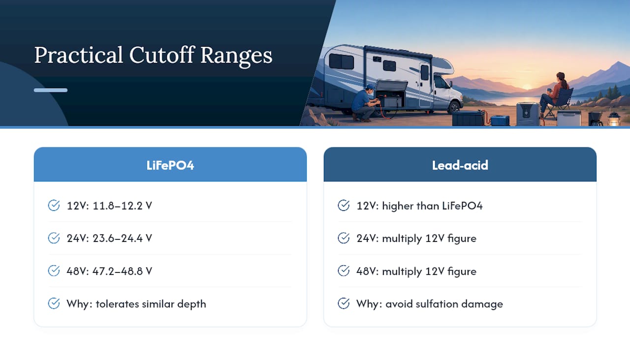
Numbers matter more than theory here, so start with real starting ranges rather than guessing. Practical tuning ranges for inverter cutoffs put LiFePO4 12V cutoffs around 11.8 to 12.2V, with lead-acid banks needing a meaningfully higher floor to avoid sulfation damage.
Scale that up for 24V or 48V banks by multiplying the 12V figures, but always verify against your specific battery’s datasheet since AGM, flooded, and gel batteries don’t discharge identically.
These ranges are starting points, not warranties. Lead-acid requires the higher floor because its discharge curve drops sharply near empty, and pulling it further risks permanent plate damage that LiFePO4 largely shrugs off at similar depths.
Three variables push these numbers around in the real world. Manufacturer specs should always override generic tables when your battery’s datasheet gives a different number. Temperature matters too: cold weather increases internal resistance, so a bank can hit its trigger point earlier in the discharge cycle than it would on a warm day, which is why some off-grid operators nudge alarm thresholds up modestly for winter. Battery age also shifts the curve, since older cells sag faster under load even when they still read a reasonable resting voltage.
How Low-Voltage Cutoff Devices Work: Trip Logic, Delay, and Hysteresis
Every LVD is really just a voltage sensor wired to a switch, but where you put that sensor and how you tune its timing decides whether it protects your battery or drives you crazy with nuisance trips.
Placement is everything. Because voltage sags under load, the LVD needs to measure voltage at the battery terminals, not at a distribution panel down the wire. If you mount the sensing point away from the battery, oversized cable and terminal placement close to the bank keep the device from tripping on panel voltage instead of true battery voltage.
Two timing behaviors keep a cutoff from misbehaving:
- Time delay prevents a brief surge, like a compressor kicking on, from tripping the disconnect on a momentary dip. Many practical LVD modules build in a delay of roughly 60 seconds before acting.
- Hysteresis is the gap between cutoff and restart voltage. Without enough gap, the device oscillates on and off as voltage bounces right around one number.
Coordination between layers matters as much as any single setting. On lithium systems, inverter cutoff should sit above the BMS floor, so the inverter shuts down gracefully before the BMS has to make a hard disconnect. Let the BMS trip first and you risk a dual-fault scenario where recovery gets complicated.
Accuracy is the variable most people overlook. A monitoring circuit accurate to roughly 0.4% will let you set cutoffs much tighter than a generic module reading with several percent of error. A sloppy sensor forces you to leave extra margin, which means you lose usable capacity you actually paid for.
Pro Tip: If your LVD trips at odd times with no obvious load spike, check the sensing wire connection before you touch the setpoint. A loose ring terminal reads voltage drop as a real event.
How to Set and Tune Your LVD: A Repeatable Test Procedure
Guessing at a cutoff number wastes capacity in one direction and risks battery damage in the other. A controlled test removes the guesswork.
- Disconnect all charging sources so solar or shore power isn’t masking the true discharge curve.
- Run your normal loads until the LVD trips at its current setting, noting the voltage at trip.
- Wait two hours with no load and no charge, letting the battery’s chemistry settle.
- Measure the resting voltage. This resting number tells you the real depth of discharge you actually reached, which the under-load voltage does not show accurately.
- Adjust the setpoint up or down to hit your target resting voltage, then repeat the test to confirm.
Set the alarm threshold first, since that gives you an early warning with zero risk while you dial things in. Set the cutoff second, once you’ve confirmed the resting voltage matches your intended depth of discharge. Restart voltage should sit high enough above cutoff that a brief charging pulse doesn’t reconnect loads prematurely; 0.4 to 0.8V of hysteresis is a reasonable starting gap for most 12V systems.
Seasonal retuning is worth the ten minutes it takes. A bank that trips cleanly at 11.9V in July may hit that same reading earlier in the discharge cycle once winter cold raises internal resistance. Nudging the alarm threshold up slightly for cold months catches this without touching your hard cutoff.
Pro Tip: Keep a simple log of trip events, dates, and outdoor temperature for the first month after installation. Patterns jump out fast, and you’ll know within a few weeks whether your settings need another pass.
Log every trip event before you call the settings final. A single test run tells you where the setpoint sits today, but a week of logged trips across different load conditions confirms the number holds up.
Choosing the Right LVD Device for Your System
Not every off-grid setup needs the same category of device, and matching the device to your loads matters as much as matching the voltage threshold.
- Small transistorized LVD modules work well for basic 12V loads like lighting circuits or a single water pump, and they’re inexpensive but usually fixed or narrowly adjustable.
- Smart battery protect devices offer programmable thresholds, delay settings, and sometimes remote monitoring, making them the better fit for mixed-load RV or cabin systems.
- Inverter or charge-controller built-in LVCs handle the job automatically for AC loads without adding a separate component, though they typically offer less fine-tuning than a dedicated module.
Whichever type you pick, check these specs before buying: voltage compatibility with your bank’s nominal voltage, continuous and surge current rating against your actual peak draw, programmability of thresholds and delay, sensing accuracy, and quiescent current draw (a poorly designed module can quietly drain your battery just by sitting there).
A dedicated external LVD generally beats relying solely on an inverter’s built-in cutoff when you have DC loads the inverter never sees, since the inverter LVC only protects what runs through it.
Installation Checklist and Wiring Best Practices
Good wiring prevents more nuisance trips than any amount of setpoint fiddling ever will.
- Mount the LVD as close to the battery terminals as physically possible. Distance introduces voltage sag, and that sag reads as a false low-voltage event even though the battery itself is fine.
- Oversize your conductors rather than sizing to the bare minimum ampacity rating; a slightly heavier gauge cable costs little and cuts voltage drop meaningfully.
- Torque every lug to the manufacturer’s spec. A loose connection adds resistance that mimics a low battery under load, and connection problems cause more nuisance trips than bad setpoints in most field reports.
- Fuse correctly on both sides of the LVD, sized to the wire gauge and the device’s rated current, not just the load.
- Keep charging conductors separate from load conductors where your device’s wiring diagram calls for it, since combining them can create sensing errors during charge cycles.
After wiring, check for low-resistance connections with a simple voltage-drop test under load. If you see more than a few tenths of a volt difference between the battery post and the LVD’s sensing terminal while a heavy load runs, you’ve got a connection problem worth chasing down before you touch a single setpoint.
Pro Tip: A $15 clamp meter and ten minutes checking voltage drop across every major connection will save you hours of troubleshooting phantom trips later.
For readers building out a full 12V distribution setup, a practical guide to safe DC distribution walks through cable sizing and layout decisions that directly affect LVD accuracy.
Testing and Troubleshooting Your LVD After Installation
Once everything is wired, run a quick functional check before you trust the system unattended. Apply a load, watch the voltage at the battery terminal and at the LVD sensing point simultaneously, and confirm they match within a small margin. A meaningful gap between those two readings points straight at wiring, not the setpoint.
- If the LVD trips earlier than expected, check for loose terminals or undersized cable before assuming your cutoff voltage is wrong.
- Cold temperatures raise internal resistance and can trigger a trip earlier in the discharge cycle than the same load would in warm weather.
- If a BMS and inverter both seem to be reacting to the same event, check that your inverter LVC sits above the BMS disconnect floor, not below it.
- Adjust time delay or alarm thresholds first when you get occasional nuisance trips from short load spikes, rather than immediately lowering the hard cutoff.
Most “bad setting” complaints turn out to be wiring issues in disguise. Fix the connection, then decide if the setpoint still needs adjustment.
Field Perspective: What Actually Goes Wrong in Off-Grid Installs
The most common LVD complaint isn’t a bad setpoint. It’s a sensing wire mounted three feet from the battery, reading voltage sag as a dead bank. Fix the wire, and half the “nuisance trips” disappear without touching a single number.
Small DC microgrids expose this fast because there’s no utility backup to hide a sloppy install. When we think through how a barn or greenhouse system should protect itself, the discipline is the same every time: sense close to the battery, delay long enough to ignore surges, and give the restart voltage real breathing room above cutoff. Systems designed with that discipline from the start need far less babysitting once they’re running.
— Chris
Western Harmonics: Hardware and Design Tools Built for This
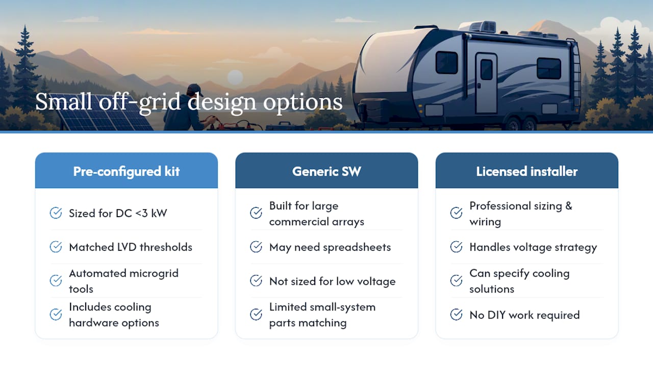
Compared to generic systems design software built for large commercial arrays, PowerMosaics.com and similar platforms sized for DC, low-voltage, and under-3kW systems are still catching up on the small-scale side. Western Harmonics offers pre-configured hardware and automated microgrid design tools intended to assist with system specifications without a spreadsheet.

If you’re assembling a small off-grid setup, the solar and battery systems catalog lists components already matched for compatible LVD thresholds, so you’re not guessing whether a given module fits your battery chemistry. For readers scoping bigger builds, the 24V versus 48V comparison explains why voltage choice changes your whole protection strategy before you buy anything. And if your project also needs to solve heat, not just power, browse the full Western Harmonics catalog for solar-powered cooling hardware sized to run on the same battery bank you’re already protecting.
If you’d rather have a licensed installer handle sizing and wiring entirely, San Diego Solar’s off-grid and battery system services are a solid option for readers who want professional design help. For everyone else ready to build it themselves, start by checking the catalog for a kit that matches your battery voltage and go from there.
Sources
For deeper technical grounding beyond this guide, the LVD selection walkthrough from Africa Field Systems Engineers covers wiring and testing in more depth. The Analog Devices battery protection article explains sensor accuracy tradeoffs, and Phocos’s LVD overview breaks down voltage versus SOC-controlled designs.
- Choosing a Low Voltage Disconnect | Africa Field Systems Engineers
- Best Inverter Low-Voltage Cutoff Settings (12V/24V/48V) | WattSizing
- Battery protection circuit (Analog Devices) — technical article
- Forum discussion and practical notes on voltage cutoff with time delay (Electronics-Lab)