

12V Voltage Drop: Calculator, Formulas, and Wiring Guide
12V Voltage Drop: Calculator, Formulas, and Wiring Guide
Exceed it, and motors stall, fridges cycle erratically, and LED drivers dim. The three fastest fixes, in order of practicality:
- Go larger gauge (drop one AWG number, e.g., 10 AWG instead of 12 AWG) to cut resistance per foot.
- Shorten the run by relocating the load or the power source closer together.
- Raise system voltage to 24V or 48V and use a local DC-DC step-down converter, which cuts current in half or more, and slashes drop dramatically.
Stretch that same wire to 25 ft one-way and the voltage drop becomes noticeably higher—exceeding typical recommended limits and worth upsizing to 10 AWG.
Key Takeaways
Table of Contents
- How to use a 12V voltage-drop calculator correctly
- Exact formulas and worked examples for DC/12V circuits
- AWG resistance reference and run-length examples for 12V
- What actually causes voltage drop and when to act
- How to reduce voltage drop: options and trade-offs
- NEC and industry guidance for acceptable voltage drop
- Quick checklist: verify a 12V wiring project before powering up
- Why voltage drop matters for off-grid 12V equipment
- The wiring mistakes we see most often
- Westernharmonics kits are engineered for reliable off-grid airflow
- Sources
How to use a 12V voltage-drop calculator correctly
Online DC voltage drop calculators display three outputs: volts lost, percent loss, and voltage at the load. Getting those numbers right depends entirely on entering the correct inputs.
System voltage is 12V for a standard lead-acid or lithium battery bank. Load current in amps is the continuous draw of the device, not its peak or startup surge. Use the nameplate rating or measure with a clamp meter under operating conditions. Conductor material defaults to copper in most calculators, and that’s the right choice for 12V DC work — aluminum is rarely used at low voltage because of its higher resistivity and corrosion sensitivity at terminals.
The input that trips up the most DIYers is wire length. For DC circuits, you must enter the round-trip length — double the one-way distance — because voltage drop occurs in both the positive and negative conductors. A 15 ft run from battery to load means 30 ft in the calculator.
AWG selection sets the resistance per foot. Most calculators let you pick from a dropdown; some let you enter mm² for metric wire. If you’re over, step down one AWG size and recalculate.
Pro Tip: *When routing wire through an engine bay, conduit in direct sun, or any space that regularly exceeds 140°F (60°C), step up one AWG size beyond what the calculator recommends.
Exact formulas and worked examples for DC/12V circuits
The core formula is straightforward:
Vdrop = I × R
Where I is current in amps and R is the total round-trip resistance of the conductor in ohms. For a DC run, R is calculated as:
R = (resistance per foot) × round-trip length (ft)
Percent drop then follows:
% drop = (Vdrop ÷ 12) × 100
AWG resistance values (copper, at 75°F) come from standard tables. Common values per 1,000 ft: 14 AWG = 2.525 Ω, 12 AWG = 1.588 Ω, 10 AWG = 0.9989 Ω, 8 AWG = 0.6282 Ω, 6 AWG = 0.3951 Ω. Divide by 1,000 to get ohms per foot.
Note that meeting ampacity alone is not sufficient — a wire sized to avoid overheating can still allow unacceptable voltage loss that shortens equipment life. Always check voltage drop as a separate calculation.
Worked examples:
-
LED lighting strip, 5A, 10 ft one-way (20 ft round-trip), 14 AWG copper R = (2.525 ÷ 1,000) × 20 = 0.0505 Ω Vdrop = 5 × 0.0505 = 0.25 V
-
12V compressor fridge, 12A continuous, 20 ft one-way (40 ft round-trip), 12 AWG copper R = (1.588 ÷ 1,000) × 40 = 0.0635 Ω Vdrop = 12 × 0.0635 = 0.76 V
-
2,000W inverter feed, ~167A at 12V, 4 ft one-way (8 ft round-trip), 2/0 AWG copper 2/0 AWG resistance ≈ 0.0967 Ω per 1,000 ft. R = (0.0967 ÷ 1,000) × 8 = 0.000774 Ω At 4 ft one-way with anything smaller than 2/0, drop climbs fast and heat becomes a real safety concern.
Percent drop grows fast at 12V because the denominator is small.
AWG resistance reference and run-length examples for 12V
The table below uses copper conductor resistance at 75°F and a round-trip length to show volts lost and percent drop at three common current levels.
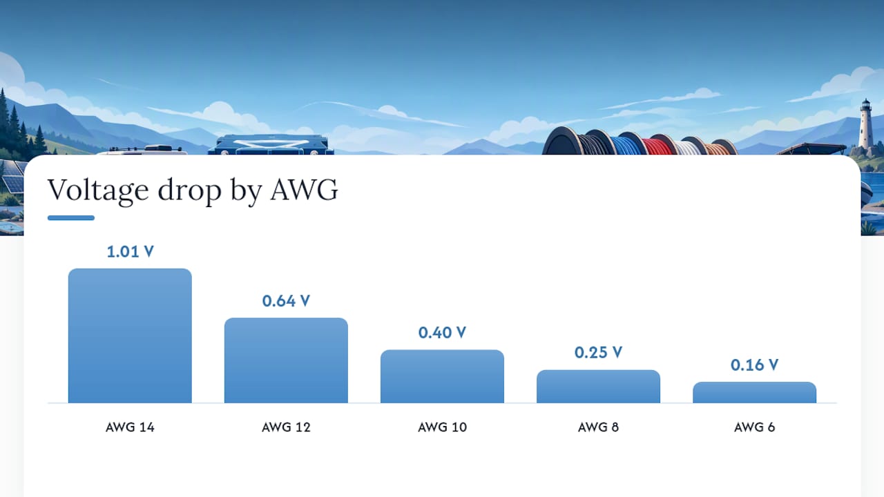
| AWG | Ω/1,000 ft | 5A @ 20 ft RT | 10A @ 20 ft RT | 20A @ 20 ft RT |
|---|---|---|---|---|
| 14 | 2.525 | 0.25 V / — | 0.51 V / — | 1.01 V / — |
| 12 | 1.588 | 0.16 V / — | 0.32 V / — | 0.64 V / — |
| 10 | 0.9989 | 0.10 V / — | 0.20 V / — | 0.40 V / — |
| 8 | 0.6282 | 0.06 V / — | 0.13 V / — | 0.25 V / — |
| 6 | 0.3951 | 0.04 V / — | 0.08 V / — | 0.16 V / — |
RT = round-trip length. Values assume copper at 75°F.
For longer runs, the picture changes quickly.
Pro Tip: When using a chassis return for the negative conductor, measure its resistance directly with a milliohm meter or by measuring voltage drop across the chassis path under load. A corroded ground strap or a long, thin chassis rail can add 0.1–0.3 Ω, which completely invalidates a calculation that assumed zero return resistance. If you can’t measure it, use a dedicated return wire and calculate round-trip length as normal.
What actually causes voltage drop and when to act
Primary causes are long wire runs, undersized gauge (high AWG number), high current draw, elevated operating temperatures, and poor or corroded connections. Each one raises the effective resistance in the circuit, and resistance is what converts electrical energy into heat instead of useful work at the load.
Distance thresholds for common 12V loads:
- LED lighting (5A or less): 14 AWG handles runs up to about 15 ft one-way before crossing 3%. Beyond that, move to 12 AWG.
- Compressor fridges and small motors (10–15A): 12 AWG becomes marginal past 10 ft one-way. Use 10 AWG for runs up to 20 ft and 8 AWG beyond that.
- High-current loads (20A+, e.g., winches, inverters, large fans): 10 AWG is the minimum starting point; most runs over 10 ft one-way need 8 AWG or larger.
- Inverter feeds (100A+): Keep runs under 6 ft one-way and use 2/0 AWG or larger. Parallel cables are often the practical answer.
Device sensitivity matters as much as the percentage. A brushless DC motor running a greenhouse fan may tolerate 10.5V before airflow drops noticeably, but a 12V compressor fridge controller may lock out below 11.5V. Loose or corroded connections are particularly dangerous because they add resistance invisibly — a connection that looks fine can add 0.2–0.5 Ω and convert a compliant circuit into a failing one. Always measure under load, not at rest.
How to reduce voltage drop: options and trade-offs
The options below are listed from most to least commonly practical for 12V DC systems.
- Increase conductor size (lower AWG number). The most direct fix. Going from 12 AWG to 10 AWG cuts resistance by 37%. The trade-off is cost and mechanical stiffness — larger cable is harder to route through tight conduit or around corners.
- Shorten the run. Moving the battery closer to the load, or the load closer to the battery, is free. Even saving 5 ft one-way on a 20A circuit can bring a marginal installation into compliance.
- Run conductors in parallel. Two 10 AWG wires in parallel equal one 7 AWG equivalent. Useful when you can’t fit a single large cable through existing conduit. Fusing and connector sizing must account for the combined current.
- Use a dedicated return wire instead of chassis ground. Chassis returns are convenient but unpredictable. A dedicated negative conductor eliminates the chassis resistance variable entirely and makes calculations reliable.
- Raise system voltage. Moving to 24V and using a DC-DC buck converter at the load cuts current in half for the same wattage, which cuts voltage drop by half. For systems with long runs and heavy loads, this is often the most cost-effective long-term solution.
Trade-off summary:
| Strategy | Cost | Ease | Flexibility | Best for |
|---|---|---|---|---|
| Larger gauge | Low-medium | Easy | High | Any run, first fix to try |
| Shorter run | Free | Moderate | Depends on layout | New installs |
| Parallel conductors | Medium | Moderate | Low in tight conduit | Retrofit, large current |
| Dedicated return | Low | Easy | High | Replacing chassis ground |
| Higher voltage | High | Complex | High long-term | Large systems, long runs |
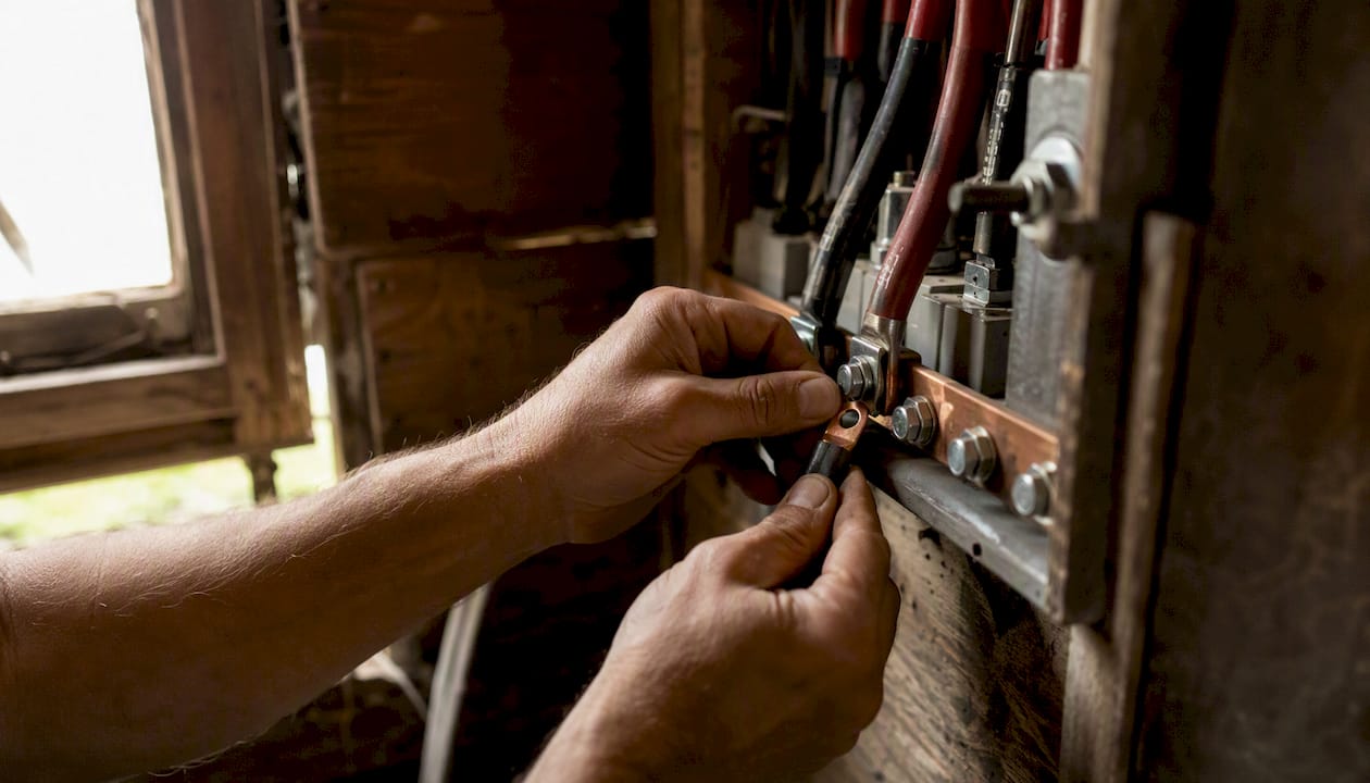
Pro Tip: For inverter battery links and main bus feeds carrying 100A or more, skip the single-cable approach entirely. Use parallel 2/0 AWG or 4/0 AWG runs, bolt large copper lugs with calibrated torque, and apply anti-oxidant compound at every terminal. A single large cable that’s awkward to route and hard to terminate reliably is worse than two well-secured parallel cables that you can actually torque properly.
Operational discipline matters too. Torque every battery terminal to spec, use quality ratchet crimpers (not pliers) on ring terminals, and protect long runs from heat sources. A well-crimped lug adds near-zero resistance; a cold solder joint or a loose set-screw terminal can add measurable ohms.
NEC and industry guidance for acceptable voltage drop
The National Electrical Code recommends a planning target of 3% voltage drop for branch circuits and a combined feeder-plus-branch target of 5% for reasonable system efficiency. These are performance recommendations, not hard-code violations — an installation that exceeds them isn’t automatically illegal, but it is likely to cause equipment problems and shortened service life.
That is a tight tolerance. At 12V, that same percentage means the difference between a motor running at full torque and one that’s struggling. Sensitive electronics, charge controllers, and brushless motor drivers often specify a minimum operating voltage of 10.5V or 11V, leaving even less headroom than the NEC target implies.
Budget drop across both segments and check device minimum-voltage specs before finalizing conductor sizes.
Quick checklist: verify a 12V wiring project before powering up
Follow these steps in order, whether you’re commissioning a new run or troubleshooting an existing one.
- Measure one-way distance from power source to load along the actual cable route, not a straight-line estimate.
- Double it for round-trip length unless you have a measured, low-resistance chassis return. If uncertain, use the full round-trip.
- Determine continuous current draw. Use the device nameplate, or measure with a clamp meter under operating load. Add 25% for motors to account for startup inrush when sizing fuses, though voltage-drop calculations use continuous current.
- Select AWG using the reference table or a calculator. Target 3% or less. If the result is borderline, step up one AWG size.
- Check all terminations. Inspect for corrosion, confirm crimp quality, and torque battery terminals to manufacturer spec.
- Fuse appropriately. The fuse protects the wire, not the device. Size it to the wire’s ampacity, not the load’s draw.
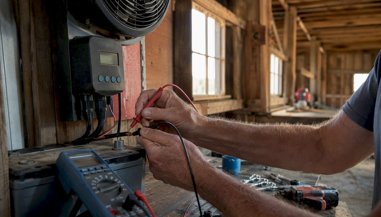
- Power up and measure voltage at the load under operating current. Use a digital multimeter across the load terminals. The reading should be within 0.36 V of battery voltage for a 3% target.
- If drop is excessive: measure voltage at the source, at the midpoint of the run, and at the load to isolate where resistance is concentrated. A large drop across a short section usually points to a bad connection, not undersized wire.
- Decide: re-run, parallel, or change voltage. If re-running is impractical and paralleling won’t fit the conduit, evaluate whether moving to 24V with a local converter makes more sense for the application.
Why voltage drop matters for off-grid 12V equipment
Voltage drop isn’t an abstract number in an off-grid greenhouse or barn. It’s the difference between a fan moving designed airflow on a 105°F afternoon and one that’s turning slowly while your plants cook.
The Westernharmonics 200W greenhouse exhaust fan kit paired with the 20" solar hanging fan represents one of the most capable off-grid airflow combinations available for greenhouse and barn applications. Both are DC brushless motors engineered to run at 12V system voltage. When wire sizing is correct, they deliver their rated CFM. When it isn’t, airflow drops, motor temperature rises, and service life shortens.
Practical wiring guidelines for these kits:
- Feed wire from battery to exhaust fan controller: use 10 AWG for runs up to 20 ft one-way; step to 8 AWG for runs up to 35 ft. Keep the battery-to-controller link as short as the installation allows.
- Hanging fan feed: the 20" hanging fan draws moderate current at 12V. For runs up to 15 ft one-way, 12 AWG is adequate; beyond that, use 10 AWG.
- Negative return: always run a dedicated negative conductor back to the battery negative terminal. Don’t rely on a greenhouse frame or metal conduit as the return path.
- Fusing: fuse each fan circuit individually at the positive terminal, sized to the wire ampacity, not the fan’s rated draw.
For greenhouse ventilation design, voltage-drop planning is one of three variables that determine whether a fan system performs as designed. The other two are panel sizing and battery capacity. Getting wire sizing wrong undermines the other two investments.
For multi-run system planning — where you’re budgeting voltage drop across a solar charge controller, battery bank, and two or three fan circuits simultaneously — a spreadsheet or calculator handles single runs well, but system-level modeling is where purpose-built software earns its place. PowerMosaics.com is one tool designed specifically for DC, low-voltage, and sub-3 kW microgrid design. It lets designers model multiple branch runs, allocate the drop budget across feeders and branches, and check device minimum-voltage compliance across the whole system in one view. For a single fan circuit, a calculator is sufficient. For a full greenhouse or barn system with multiple loads, battery sizing, and PV input, a tool like PowerMosaics.com speeds the work considerably and reduces the risk of an undersized run hiding in a complex system.
The wiring mistakes we see most often
The single most common error in 12V wiring is using one-way distance in a round-trip calculation. A builder measures 18 ft from battery to load, enters 18 ft in the calculator, and sizes wire accordingly. This error is so common that most professional DC designers double-check the length input before anything else.
The second mistake is sizing for ampacity and assuming voltage drop is covered. A wire can be thick enough to avoid overheating and still allow enough drop to cause real performance problems. Ampacity and voltage drop are separate checks, and both are required.
Chassis returns are the third recurring problem. A builder uses the vehicle frame or greenhouse metal structure as the negative return, calculates assuming zero resistance, and gets a result that looks fine on paper. In the field, a corroded ground strap or a long, thin structural member adds enough resistance to push the circuit out of spec. The fix is simple: run a dedicated return wire and measure under load before closing up conduit or cable management.
Inrush current catches people off-grid too. A compressor fridge or brushless fan motor can draw 3–5 times its continuous current for the first half-second of startup. Fuses sized to continuous draw trip on startup; fuses sized to inrush may not protect the wire adequately. The right approach is to size the fuse to the wire’s ampacity and verify the wire handles inrush without excessive voltage sag at the motor terminals.
The single most useful habit: always measure voltage at the load under operating current before finalizing conduit, cable ties, and connectors. It takes two minutes and catches every mistake the calculator missed.
Westernharmonics kits are engineered for reliable off-grid airflow
The 200W greenhouse exhaust fan kit and the 20" solar hanging fan are designed to work together as a complete off-grid airflow system. The exhaust fan moves hot air out; the hanging fan circulates air through the growing zone. Together, they deliver the kind of airflow performance that keeps a greenhouse productive through a summer heat event — provided the wiring is done right.

Westernharmonics kits include wiring guidance, recommended fuse ratings, and battery sizing notes specific to each product. Every kit is built for real off-grid conditions: dust, heat, vibration, and years of unattended operation. For readers planning a full system, the Westernharmonics system design tool walks through load calculations, battery sizing, and wire run planning in one place. Browse the full off-grid cooling catalog to find the right combination for your barn, greenhouse, or workshop.
Sources
These tools and references support the calculations and guidance in this article.
- Understanding voltage drop (Enginist)
- 12V DC voltage drop calculator guidance (TradeCalcs)
- Voltage drop basics and NEC guidance (IEWC)
- Wire gauge and voltage drop guidance (ServiceWire)
- Voltage drop problems and solutions (Powerelectra)