

DC Brushless Fans for Engineers: 50,000+ Hour Life in Off Grid Solar
DC Brushless Fans for Engineers: 50,000+ Hour Life in Off Grid Solar
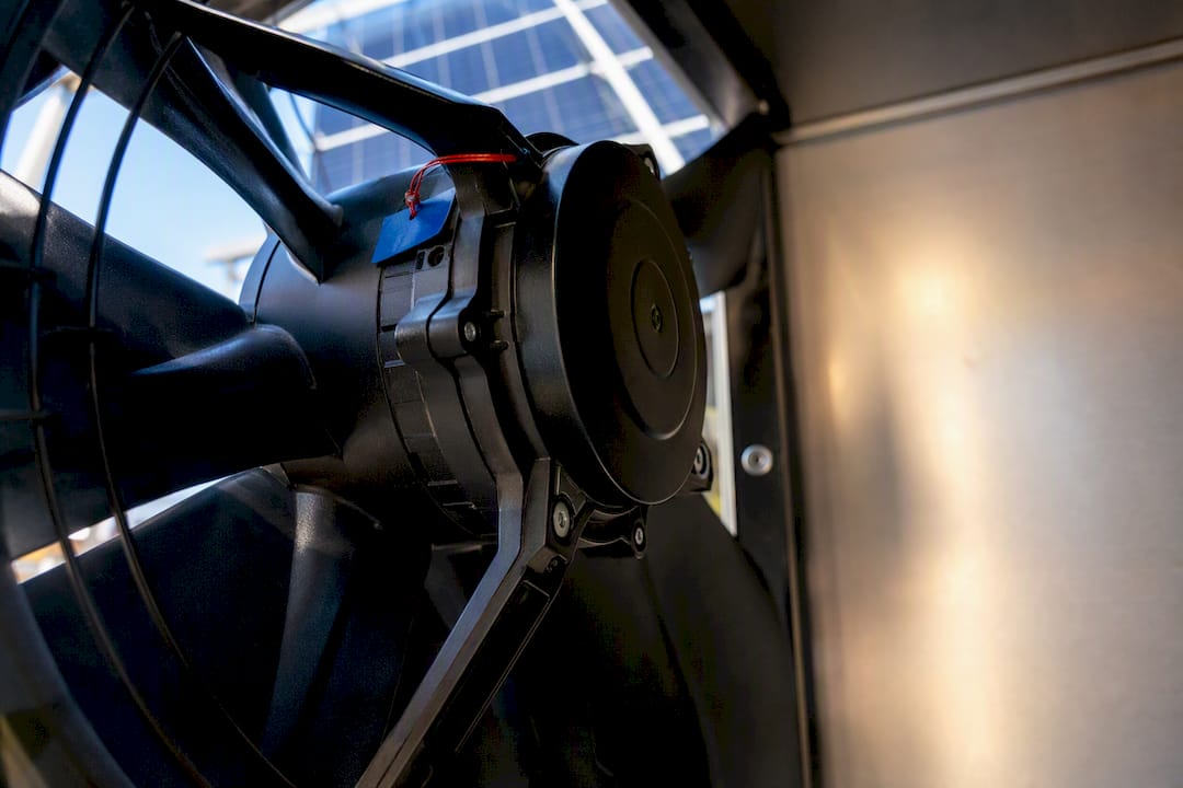
A DC brushless fan uses electronic commutation instead of mechanical brushes to spin a permanent-magnet rotor around a fixed stator, and that single design choice is why engineers specify them over brushed or AC alternatives. Pick a BLDC fan when you need efficiency, precise speed control, and long service life without maintenance. They fit best in electronics cooling, HVAC assemblies, and solar or off-grid systems where every watt and every service call counts.
TL;DR:
- Bearings significantly influence fan lifespan, with ball bearings lasting longer than sleeve bearings, especially in continuous-duty or horizontal applications.
- Proper system impedance modeling and matching P-Q curves ensure the fan operates at its optimal point, maximizing efficiency and performance.
- Control method choices impact noise, efficiency, and startup reliability, with FOC and sensorless control offering smoother operation than basic trapezoidal commutation.
- Sealed construction and durable bearings are critical for off-grid or dusty environments, where exposure to dust, humidity, and temperature fluctuations can cause failure.
- Selecting the right fan requires understanding thermal load, impedance, voltage, and environment first, rather than simply choosing based on datasheet max specifications.
Table of Contents
- How Do Brushless DC Fans Work?
- What Components Determine a Fan’s Performance and Lifespan?
- Which Control Method Should You Choose: PWM, FOC, or Sensorless?
- How Efficient and Durable Are BLDC Fans, and How Do You Read a P-Q Curve?
- How Do You Select the Right BLDC Fan for Your Application?
- What Causes BLDC Fan Failures, and How Do You Prevent Them?
- What Western Harmonics Has Learned Building Off-Grid BLDC Fans
- Where to Read Deeper on BLDC Fan Engineering
- Get the Right Fan and Design Tools for Your DC System
- The Engineering Reality Behind the Marketing
- Sources
How Do Brushless DC Fans Work?
A DC brushless fan replaces the mechanical brush-and-commutator assembly found in older motors with an electronic speed controller (ESC) that switches current through the stator windings in a precise sequence. The rotor carries permanent magnets; the stator stays stationary and energized. As the controller fires each winding phase, the resulting magnetic field pushes against the rotor magnets through basic Lorentz force interaction, and the rotor turns. This is the core of electronic commutation, and it’s what lets these motors run without the wear, arcing, and electromagnetic interference (EMI) that brushed designs generate.
The controller needs to know rotor position to fire the right phase at the right moment. It gets that data one of two ways:
- Hall-effect sensors embedded near the rotor report position directly, giving reliable low-speed and startup performance.
- Back-EMF detection reads the voltage generated by the spinning rotor in the unpowered winding, avoiding sensor cost but requiring the rotor to already be moving fast enough to generate a readable signal.
Input voltage and pulse-width modulation (PWM) duty cycle set how fast the rotor spins and how much torque it delivers. Raise the duty cycle, and average voltage to the windings climbs, pushing RPM and torque up together. Manufacturer white papers on DC brushless cooling fan behavior show datasheets specify a nominal speed and tolerance band across a defined voltage range, which matters when your supply voltage sags under load or drifts with battery state of charge.
What Components Determine a Fan’s Performance and Lifespan?
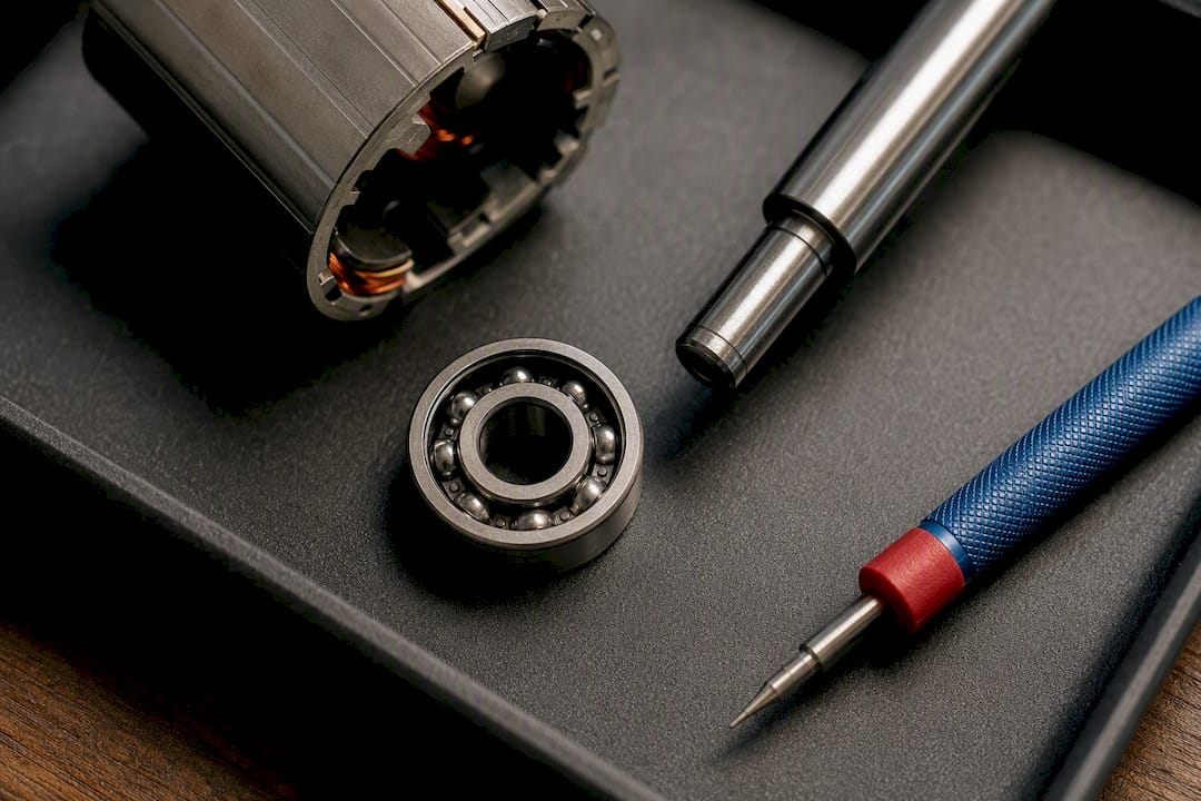
Four parts decide how a BLDC fan performs and how long it survives in the field: bearings, magnets, impeller geometry, and the driver PCB.
- Bearings. Sleeve bearings cost less but wear faster under heat and orientation stress. Ball bearings cost more but typically deliver a longer mean time between failures (MTBF), especially in fans that run continuously or mount horizontally.
- Magnets. Neodymium magnets pack more power into a smaller rotor, raising power density and letting a compact fan produce meaningful airflow.
- Impeller geometry. Blade pitch, count, and diameter set the balance between static pressure and volumetric airflow (CFM). Steeper pitch favors pressure; flatter, wider blades favor volume.
- Housing and sealing. Potted electronics and higher IP ratings keep dust and moisture off the driver PCB and windings, which matters enormously once a fan leaves a climate-controlled cabinet.
Sealed BLDC construction is one reason these motors hold up where brushed motors fail. Brushed designs need exposed windings and commutator contact, which invite dust and humidity damage that a sealed brushless housing simply avoids.
Pro Tip: Check the bearing spec before the motor spec. A premium BLDC motor paired with a cheap sleeve bearing will fail at the bearing long before the windings ever degrade.
Which Control Method Should You Choose: PWM, FOC, or Sensorless?
The driver topology you pick decides efficiency, acoustic behavior, and how the fan integrates with your host system. Three approaches dominate the market.
- Trapezoidal (six-step) commutation is the simplest and cheapest, switching current in discrete steps. It works fine for basic speed control but introduces torque ripple that can translate into audible noise.
- Field Oriented Control (FOC) commutates more smoothly by continuously calculating the optimal current vector, cutting torque ripple and improving efficiency at partial loads. FOC reduces audible switching noise compared with trapezoidal drive when implemented correctly.
- Sensorless back-EMF control cuts sensor cost but needs a forced-commutation startup routine to establish rotor position at zero RPM, which is why high-inertia impellers or cold-start applications often lean on Hall sensors instead.
PWM switching frequency matters just as much as the control method. Frequencies chosen poorly land in the audible range and produce a high-pitched whine; pushing frequency higher or pairing PWM with FOC largely eliminates that artifact. On the host side, expect one of three interfaces: simple PWM with a tach return line, a 0 to 10V analog control signal, or a digital bus like CAN or LIN for fans integrated into larger equipment networks.
How Efficient and Durable Are BLDC Fans, and How Do You Read a P-Q Curve?
Efficiency and lifespan are where brushless fans earn their premium price. Typical BLDC fan lifetimes run from tens of thousands of hours up toward 50,000 or more, and efficiency commonly exceeds brushed equivalents by a meaningful margin, largely because there’s no brush friction or arcing loss to overcome. Bearing type is still the deciding variable. A ball-bearing fan in a temperature-controlled enclosure will outlast a sleeve-bearing fan running hot and horizontal by a wide margin.
The datasheet’s pressure-versus-airflow (P-Q) curve is the single most useful chart for matching a fan to your system. It plots static pressure on one axis against volumetric airflow on the other, and the point where that curve crosses your system’s own impedance curve is the actual operating point your fan will hit, not the peak numbers printed on the box.
| Metric | Typical Range | What Drives It |
|---|---|---|
| Efficiency vs. brushed equivalent | Notably higher | No brush friction/arcing losses |
| Rated lifetime | Tens of thousands to 50,000+ hours | Bearing type, thermal load, duty cycle |
| Noise source | PWM switching artifacts | Switching frequency, commutation method |
Noise mitigation follows directly from the control section above: FOC and well-chosen PWM frequencies suppress the whine that trapezoidal drives at low switching rates tend to produce.
How Do You Select the Right BLDC Fan for Your Application?
Specification should follow a fixed sequence, not a parts catalog search. Work through it in this order:
- Map thermal load to required airflow. Calculate the heat you need to remove, then convert that to a CFM target before looking at any fan spec sheet.
- Model system impedance. Filters, grilles, ducting, and enclosure geometry all add resistance; know your system’s impedance curve before comparing P-Q curves.
- Lock the voltage domain and control interface. Match the fan to your supply (12V, 24V, 48V) and to whatever control signal your host already generates, whether that’s PWM, 0 to 10V, or a bus protocol.
- Specify bearing type and IP rating for the environment. A greenhouse or barn deployment needs a different bearing and seal spec than a server rack.
- Request P-Q curves, accelerated life test (ALT) data, and EMI reports from the vendor. Manufacturer guidance on brushless fan selection consistently starts with impedance mapping before any part number gets chosen, and it’s worth reading before you commit.
If your project sits below 3kW and runs on DC or low-voltage architecture, this same sequence, thermal load, impedance, voltage domain, then component specification, is exactly what dedicated system design software should walk you through, rather than leaving you to cross-reference datasheets by hand. For static pressure thresholds specifically, our own breakdown of axial versus centrifugal fan selection covers where each impeller type wins.
What Causes BLDC Fan Failures, and How Do You Prevent Them?
Bearing wear is the most common failure mode, showing up as rising noise, RPM drift under constant voltage, or eventual stall. Root causes are usually thermal stress, wrong mounting orientation for the bearing type, or grease breakdown from prolonged high-temperature operation.
- Bearing wear: Use ball bearings for continuous-duty or non-vertical mounting, and match grease spec to your ambient temperature range.
- RPM drift: Add closed-loop tach feedback so the controller compensates for load or voltage changes instead of running open-loop.
- Startup stall: Specify soft-start ramping and, for sensorless designs, confirm the driver includes forced-commutation startup pulses so rotor position gets established at zero RPM even with high impeller inertia.
- EMI: Shield driver leads, ground the housing properly, and add snubbers across switching elements; poor PCB layout is the usual culprit when a fan starts injecting noise into nearby sensors.
Pro Tip: If RPM drifts more than a few percent as your solar battery voltage sags through the day, that’s a controller without proper voltage compensation, not a bad fan. Check the driver spec before replacing the unit.
What Western Harmonics Has Learned Building Off-Grid BLDC Fans
Westernharmonics has spent years building solar-powered fan kits for barns, greenhouses, and workshops where grid power isn’t reliable, and every lesson from that fieldwork points back to the same principle covered above: sealed construction and rugged bearings aren’t optional in dusty, humid, temperature-swinging environments. Our comparison of AC and DC fans for off-grid solar ventilation walks through why brushless DC wins in these conditions specifically.
Practical takeaways from that experience:
- Off-grid voltage rarely stays flat, so fan controllers need real tolerance for sag and drift, not just a nominal spec.
- Potted driver electronics and sealed bearings hold up against barn dust and greenhouse humidity far longer than open designs.
- A brushless greenhouse exhaust fan built for these conditions gives you a field-proven reference point when specifying your own system.
Where to Read Deeper on BLDC Fan Engineering
For datasheet interpretation and P-Q curve fundamentals, manufacturer white papers remain the best primary source, particularly the DC brushless cooling fan behavior documentation covering speed tolerance against input voltage. For a plain-language primer on the motor physics itself, HowStuffWorks’ brushless motor explainer covers the fundamentals well. For system-level energy efficiency context that applies whether you’re running fans or full off-grid power setups, our partner’s energy efficiency guide for homeowners is worth a read.
Get the Right Fan and Design Tools for Your DC System
Everything above only matters if you can turn it into a working system without weeks of manual datasheet comparison. That’s the gap between traditional fan selection and modern systems design software for DC, low-voltage and sub-3kW projects: most engineers still map thermal load, impedance, and voltage domain by hand, cross-referencing PDFs from three different vendors before they even get to a bill of materials.
Efforts exist to close that gap by pairing field-tested brushless hardware with system design tools built specifically for off-grid DC work rather than generic HVAC software scaled down. If you’re specifying a fan for a small greenhouse or shed, the Kit# 1505-HG 10W Solar Powered Fan Kit is a proven starting point with documented performance instead of a spec sheet promise. For larger airflow needs, the Solar Power 2 Fan System scales up without forcing you into a different control architecture. Browse the full Western Harmonics catalog to compare kits against the selection criteria covered above before you commit to a part number.
The Engineering Reality Behind the Marketing
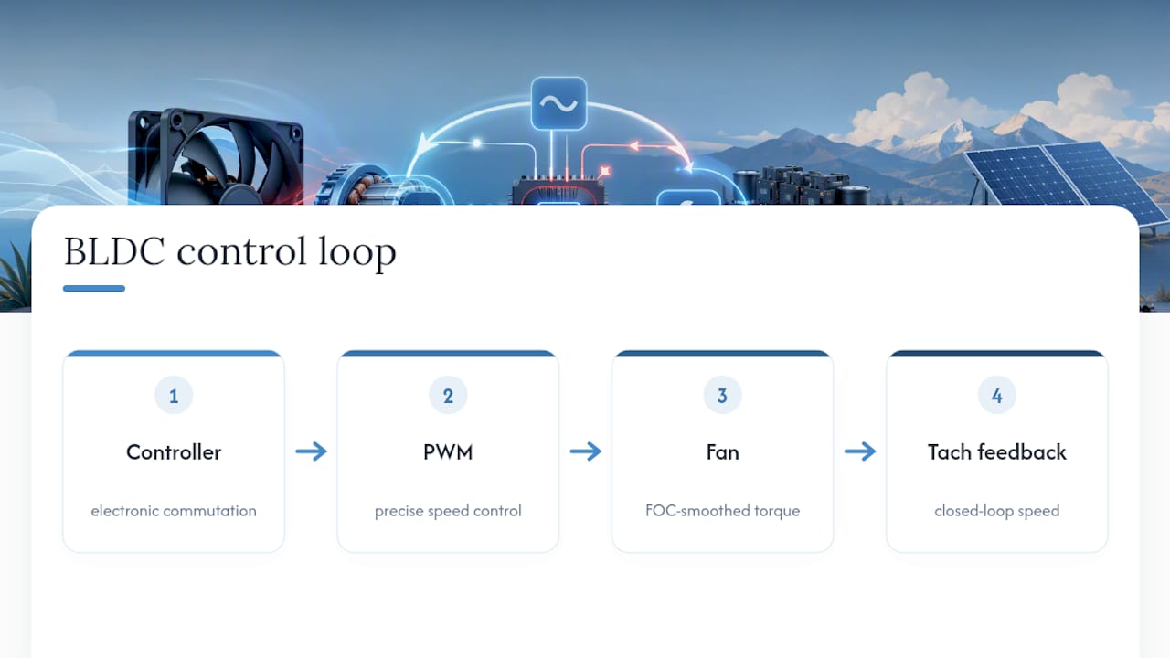
Most explainers on this topic stop at “brushless is better because no brushes.” That’s true but incomplete, and it undersells the part that actually matters for system design: the value of a BLDC fan isn’t the absence of brushes, it’s what electronic commutation makes possible once it’s there. Precise PWM control, FOC-smoothed torque, closed-loop tach feedback, none of that exists without the electronic controller that brushless architecture requires in the first place.
Where I think the conventional advice falls short is in treating fan selection as a component lookup instead of a system problem. Engineers pull a CFM number off a datasheet, match it loosely to a duct size, and call it done. That skips the P-Q curve entirely, and it’s exactly why fans get returned as “underperforming” when they were simply never matched to system impedance in the first place.
If you take one thing from this explainer, prioritize the impedance mapping step before you touch a vendor catalog. Everything downstream, bearing choice, control interface, voltage domain, is easier to get right once you know the actual operating point your fan needs to hit.
— Chris
Sources
- Brushless DC electric motor
- How does a brushless electric motor work? | HowStuffWorks
- DC Brushless Cooling Fan Behavior
- Master DC Brushless Fan Motors: Principles, Structure, and Benefits - Gagner-Toomey Associates