

25 kHz PWM: How Hobbyists and PC Builders Keep 4 Pin Fans Safe
25 kHz PWM: How Hobbyists and PC Builders Keep 4 Pin Fans Safe
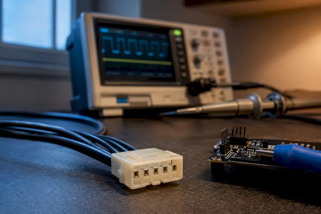
PWM fan speed control uses a timed on/off signal on the fan’s dedicated control pin to change duty cycle, and therefore speed, without touching the power rail. The rule that matters most: apply PWM at roughly 25 kHz on the 4th control pin only, sharing ground with the fan and never on the +12V supply line itself. Get that one detail wrong and you risk cooking the fan’s internal motor driver instead of just controlling it.
TL;DR:
- Proper implementation requires PWM at roughly 25 kHz on the control pin only, never on the power line or +12V supply line, to prevent damage.
- The control signal’s duty cycle determines the average energy delivered to the fan, with 30% duty cycle roughly halving the full RPM and torque.
- Correct wiring involves a shared ground and a pull-up resistor on the tach line, with a recommended PWM frequency of 21 to 28 kHz for clean tach signals.
- BIOS, motherboard utilities, or Linux tools can automate PWM fan control, but paths may shift on reboots, requiring careful configuration.
- For uninterruptible operation, set minimum start RPM based on fan specs, avoid low-frequency PWM to prevent whine, and verify signals with a scope before final wiring.
Table of Contents
- What Actually Changes When You Adjust PWM Fan Speed Control
- Fan Interfaces And Tach Signal Behavior Under PWM
- Building A Safe PWM Driver Circuit For Fans
- Controlling PC Fans Through BIOS, Software, And Linux
- Fixing Whining Fans, Bad Tach Readings, And Stall Problems
- PWM Fan Control In Off-Grid And DC Power Systems
- Our Take: Default Settings That Save You A Rebuild
- When A Solar-Powered DC Fan Kit Makes More Sense
- Sources
What Actually Changes When You Adjust PWM Fan Speed Control
Duty cycle, not voltage, does the work here. A PWM signal switches full voltage on and off rapidly, and the percentage of time it stays “on” during each cycle determines how much average energy reaches the fan’s motor driver. A 30% duty cycle delivers roughly 30% of the energy a fan sees at full tilt, and the internal driver electronics translate that into a proportional drop in torque and RPM.
Frequency matters just as much as duty cycle. Run PWM too slow, somewhere in the audible range, and you get an actual whine or buzz as the motor coils energize and de-energize at a pitch your ears can pick up. Analog Devices recommends staying above 20 kHz specifically to push that switching noise out of human hearing range, and doing so also preserves a wider usable control range, down to roughly 10% of full speed, compared with older linear voltage-reduction schemes.

That’s the real advantage PWM has over simply dropping voltage with a resistor or linear regulator: the fan’s internal electronics stay fully powered at all times. Only the effective energy delivered to the motor windings changes. That’s why properly implemented PWM fans can spin reliably at low speeds where a voltage-starved fan would just stall.
Fan Interfaces And Tach Signal Behavior Under PWM
Fan connectors tell you what kind of control you’re working with before you ever touch a wire:
- 2-pin fans carry only ground and +12V. No speed feedback, no PWM input, voltage reduction only.
- 3-pin fans add a tachometer wire, giving you RPM feedback, but speed control still happens through voltage, not a dedicated PWM line.
- 4-pin fans add the true control pin, following the Intel 4-wire PWM specification: pin 1 ground, pin 2 +12V, pin 3 tach/sense, pin 4 PWM control.
The tach wire outputs two pulses per full rotation, so RPM works out to frequency in Hz times 60, divided by two, according to Noctua’s PWM specifications white paper. Low-frequency or sloppy PWM can chop that tach signal into unreadable fragments. High-frequency PWM, done right, keeps the fan’s internal electronics powered continuously, which keeps tach pulses clean and readable.
Building A Safe PWM Driver Circuit For Fans
Get the frequency and the wiring right and a PWM fan control setup is genuinely simple to build. Get it wrong and you’ll either hear it, or you’ll damage the fan.
- Target 25 kHz on your microcontroller’s timer output, staying within the 21 to 28 kHz range Noctua supports.
- Wire the PWM output only to pin 4, the control pin. Never route a PWM signal onto the +12V power line.
- Tie your microcontroller’s ground directly to the fan’s ground pin. Shared ground is not optional; without it, your duty cycle reading at the fan is meaningless.
- Add a pull-up resistor on the tach line if your fan or motherboard doesn’t already supply one internally.
- Power the fan itself from a stable, adequately rated 12V rail, separate from your microcontroller’s logic supply if that supply can’t handle motor back-EMF spikes.
Many microcontroller PWM outputs are open-drain or need a buffer stage to drive a fan’s control pin cleanly. A basic CMOS inverter or a small logic-level driver chip between your timer output and the fan solves compatibility issues before they show up as erratic speed behavior.
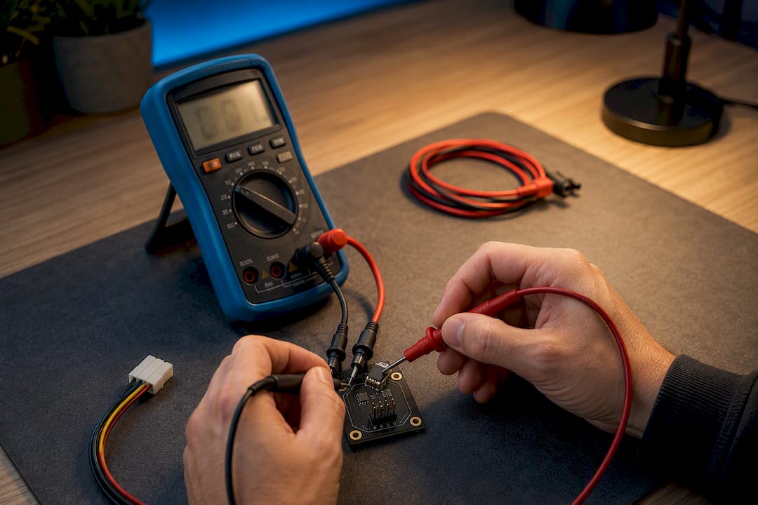
Pro Tip: Before wiring anything permanent, bench test your PWM output on a multimeter set to average DC voltage. A clean, stable reading that shifts predictably as you change duty cycle tells you your timer configuration is solid before the fan is even connected.
Controlling PC Fans Through BIOS, Software, And Linux
Most PC builders never touch a microcontroller. Motherboards handle PWM fan control internally, and the 4-pin headers apply the same duty-cycle logic straight from firmware.
- BIOS/UEFI fan curve menus let you map temperature to duty cycle directly, and the platform-level ACPI fan device specification defines how firmware can expose fine-grained fan performance states from 0 to 100%.
- Vendor software (motherboard maker utilities) layers a friendlier interface over the same BIOS-level controls, useful for RGB syncing or per-fan curves, but it’s rarely necessary once you’ve set a curve in firmware.
- On Linux,
lm_sensorspluspwmconfigbuilds an/etc/fancontrolfile with MINSTART, MINTEMP, and MAXTEMP values tuned to your hardware, as detailed on the ArchWiki fan speed control page. - The kernel’s hwmon PWM fan driver exposes raw sysfs attributes like
pwm1(0 to 255) andfan1_input, useful if you’re scripting your own control logic instead of relying on fancontrol.
One caveat worth knowing before you spend an evening debugging: hwmon paths can shift between reboots if you’re loading multiple sensor modules, which silently breaks a working fancontrol setup. Pin your paths or module load order once you’ve got a configuration you like.
Fixing Whining Fans, Bad Tach Readings, And Stall Problems
Most fan speed automation problems trace back to one of four causes.
- Audible whine or buzz: Your PWM frequency is too low. Push it above 20 kHz, matching the fan’s own spec sheet if one is published.
- Erratic or missing tach readings: Chopped tach pulses from poor PWM implementation. Higher-frequency PWM or pulse-stretching circuitry inside better fan drivers fixes this.
- Fan won’t start at low duty cycle: Every fan has a minimum start speed. The Intel 4-wire spec requires vendors to publish a minimum RPM at 30% or less of maximum, and fans handle duty cycles below that floor in one of three ways: Type A stops the fan entirely, Type B holds it at minimum RPM, Type C ramps back up. Set your MINSTART and MINPWM values with that behavior in mind, not just a guess.
- Uncertain signal quality: A cheap logic analyzer or oscilloscope shows you frequency, duty cycle, and tach pulses directly, which beats guessing from RPM readouts alone.
Quick wiring checklist before you power anything on: confirm shared ground, confirm a pull-up on the tach line if needed, confirm PWM lands on pin 4 only, and confirm your intended frequency with a scope rather than trusting a datasheet default blindly.
PWM Fan Control In Off-Grid And DC Power Systems
PWM fan speed control and PWM solar charge controllers share a name and little else. One is a signal that adjusts a fan motor’s duty cycle. The other regulates how a solar panel charges a battery. Don’t confuse them when you’re speccing a DC ventilation system.
Fans still need a stable, properly sized DC supply regardless of how your battery gets charged. A small 12V off-grid setup can run a PWM charge controller for lower cost, while larger arrays benefit more from MPPT’s better panel harvest. Either way, size your wiring and controller for the fan’s actual current draw, not just the panel’s rated output. Interestingly, some hobbyists have found that PWM fan loads on constrained panels can shift the panel’s apparent operating point, though that’s a side effect, not a substitute for proper MPPT design where it counts.
Our Take: Default Settings That Save You A Rebuild
Our recommendation for most builders: stick with 4-pin PWM fans, set the frequency near 25 kHz, and let a BIOS fan curve do the work on a PC. Save microcontroller-driven PWM for custom rigs where firmware control isn’t an option.
Bench test with a stable 12V supply before final assembly. Verify tach pulses read clean, and measure your actual PWM waveform rather than trusting a chip’s default timer settings. Set MINSTART conservatively, and leave margin on your driver’s current rating. That margin is what separates a fan that lasts years from one you’re rewiring in six months.
— Chris
When A Solar-Powered DC Fan Kit Makes More Sense
If your project lives somewhere without reliable mains power, a barn, a greenhouse, a remote workshop, PWM microcontroller tinkering solves the wrong problem. Some companies build solar-powered fan kits designed to run directly off battery-backed DC power, no motherboard header or BIOS menu required.

For a single remote enclosure, the 10W Solar Powered Fan Kit gets airflow moving without any grid connection at all. Larger spaces or setups needing redundancy do better with the 200W Solar Hanging Fan Kit with battery backup, which keeps running through cloudy stretches. Readers wiring a fan directly to a panel or battery bank should read the solar fan wiring guide first. It walks through direct-wire, controller, and battery-backed configurations so you size the system correctly before you buy anything. Browse the full lineup in the Westernharmonics catalog and pick the kit that matches your site’s power situation.
Sources
- Why and How to Control Fan Speed for Cooling Electronic Equipment | Analog Devices
- Fan speed control - ArchWiki