

MC4 Crimping: Stop Failures, 7.0 mm, 50 lb, 3.4 N·m for Hobbyists
MC4 Crimping: Stop Failures, 7.0 mm, 50 lb, 3.4 N·m for Hobbyists
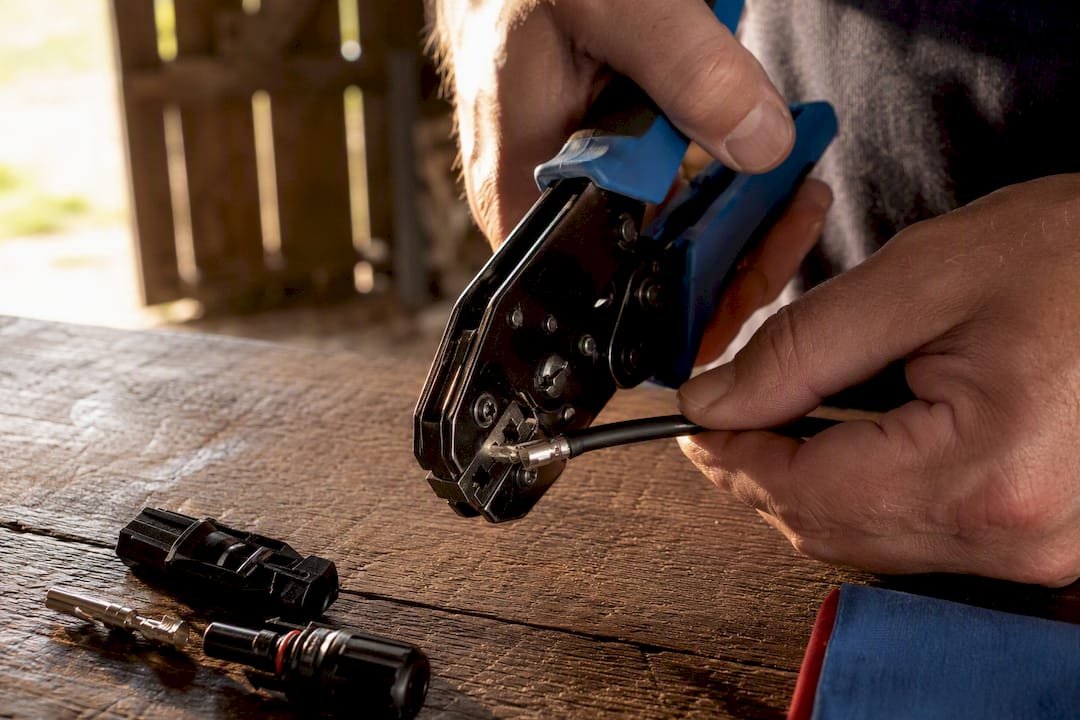
Crimp MC4 connectors using a ratcheting crimper with matched hexagonal dies, strip the conductor to roughly 7.0 mm, seat it fully, and run the crimper through a complete ratchet cycle. Torque the cable gland to about 3.4 N·m, then confirm the work with a pull test and a continuity check. Everything past this point explains why each of those numbers matters and how to hit them consistently on a bench or a rooftop.
TL;DR:
- Proper crimping requires a dedicated ratcheting MC4 crimper with matched dies and a full ratchet cycle to ensure a secure, symmetrical, and reliable connection.
- Confirm the contact is fully inserted, the crimp shows a clean hex shape, and the gland nut is torqued to about 3.4 N·m to maintain seal integrity and water resistance.
- Conduct a pull test of at least 50 pounds, check continuity and resistance with a multimeter, and verify gland torque to catch most field defects before deployment.
- Avoid common mistakes such as improper strip length, nicked strands, mixing brands, or skipping the gland or cap during assembly to prevent connection failure.
- For long-term durability, ensure proper weatherproofing by correctly seating gaskets and routing cables to prevent moisture ingress and thermal stress over time.
Table of Contents
- What Tools and Materials Do You Need Before You Start?
- How Do You Crimp an MC4 Connector Step by Step?
- What Should You Check to Verify a Good MC4 Crimp?
- What Are the Most Common MC4 Crimping Mistakes?
- What Standards and Best Practices Should You Follow?
- How Do You Weatherproof MC4 Connections for the Long Term?
- An Installer’s Honest Take on Trusting the Process
- Fewer Field Crimps, Same Reliable Result
- Sources
What Tools and Materials Do You Need Before You Start?
Half the bad crimps we hear about trace back to one thing: someone tried to make do with pliers or a “universal” crimper that doesn’t match the MC4 contact geometry. Don’t do that. You need a dedicated kit, and it’s not expensive relative to the panels you’re protecting.
Here’s what belongs on your bench:
- A ratcheting MC4 crimper with hexagonal dies sized for your wire gauge
- A calibrated torque wrench or dedicated MC4 torque spanner for the gland nut
- Precision wire strippers with an adjustable depth stop
- MC4 disconnect wrenches for tightening and separating housings
- A multimeter for continuity and resistance checks
- Dielectric grease for the contact area
Buy same-brand MC4 housings and contacts, and use PV-rated, tinned-copper cable rather than generic THHN or CCA (copper-clad aluminum) wire. Mixed brands and non-PV conductors invite corrosion and higher contact resistance down the line. On tools, a mid-range IWISS-style ratcheting crimper handles most hobby and small off-grid jobs fine; professional-grade tools like the Staubli PV-CZM-22100 cost far more and make sense mainly for installers running crimps daily.
Pro Tip: Buy two or three extra contacts and a foot of scrap cable before you touch your real wire run. Practice crimps cost nothing and teach your hands what “full ratchet” actually feels like.
How Do You Crimp an MC4 Connector Step by Step?
This is the sequence that matters, in the order it matters. Skip a step, especially the first one, and you’ll be redoing work you thought was finished.
- Slide the gland components on first. Before you strip or crimp anything, slide the cap nut, sealing gland, and washer onto the cable in the correct order. Forget this and you’ll have to cut the crimped contact off and start over.
- Set your strip length. Adjust your stripper to a stop at 7.0 mm, which sits inside the commonly cited 6 to 7.5 mm range for MC4 pins. Strip cleanly. A stripper without a depth stop is how you nick strands.
- Insert the conductor into the contact barrel. Push it in until copper is visible in the inspection window and no insulation has crept into the barrel. If you can see bare wire past the barrel or insulation jammed inside, pull it and start the strip again.
- Match the die to your wire gauge and seat the terminal. Center the contact in the correct hex die cavity. Off-center placement produces a lopsided crimp that looks fine from one angle and fails from another.
- Run the crimper through a full ratchet cycle. This is the step people rush. The ratchet mechanism exists specifically so you can’t release the handle early and walk away with a half-formed crimp. Let it run to release on its own.
- Inspect the crimp shape. You’re looking for a clean hexagonal imprint around the barrel, no cracks, no flaring.
- Pull-test the contact. Give it a firm 50-pound tug by hand before it goes anywhere near a housing. The IEC 60352-2 lab standard tests to roughly 310 N, well above what you can generate by hand, but a 50 pound field tug (about 220 N) catches the crimps that were never going to survive.
- Insert the contact into the housing until you hear and feel a click. That click is the locking tab seating. No click means the contact isn’t secured.
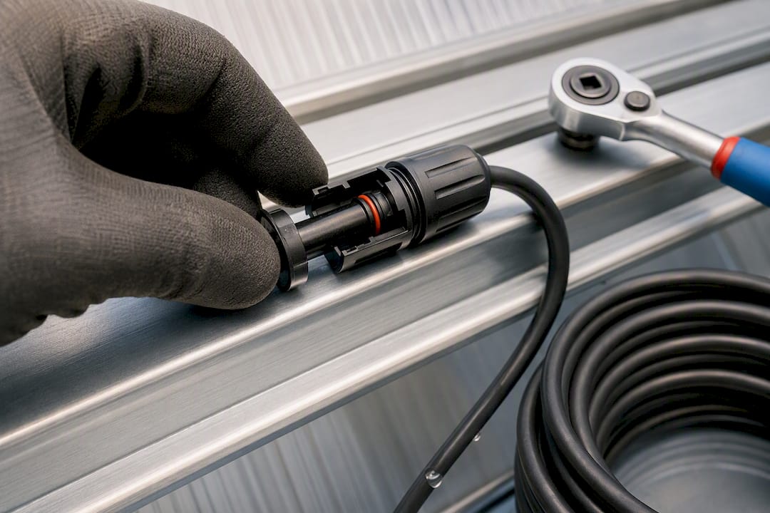
- Hand-tighten the gland nut, then finish with a torque spanner. Bring it to roughly 3.4 N·m, about 25 inch-pounds. That figure protects the IP rating of the connector by keeping the seal compressed without cracking the housing.
- Run a continuity and resistance check with your multimeter, and add a light coat of dielectric grease to the contact if your manufacturer’s guide recommends it.
By the numbers: A field-ready MC4 crimp holds to a 7.0 mm strip length, survives a 50 lb (≈220 N) pull test, meets a 310 N lab tensile spec under IEC 60352-2, and locks down at 3.4 N·m of gland torque.
Manufacturer guides back this sequence up directly. Tesla’s field-made MC4 quick guide walks installers through the same order of operations: verify strip length, position the die correctly, and use the proper disconnect tool rather than forcing housings apart by hand.
What Should You Check to Verify a Good MC4 Crimp?
A good crimp announces itself if you know what to look for. Run through this before any connector leaves your bench:
- Visual check: symmetrical hexagonal die marks, no insulation inside the barrel, no cracked or flared metal, copper visible in the inspection window.
- Pull test: a firm 50 lb (≈220 N) tug by hand. The lab reference in IEC 60352-2 sets tensile strength requirements around 310 N, but you’re not trying to hit lab numbers with your hands. You’re trying to catch the crimps that would fail long before 220 N.
- Continuity and resistance check: a multimeter reading that’s stable and low. Fluctuating or high resistance readings mean the crimp isn’t making full contact.
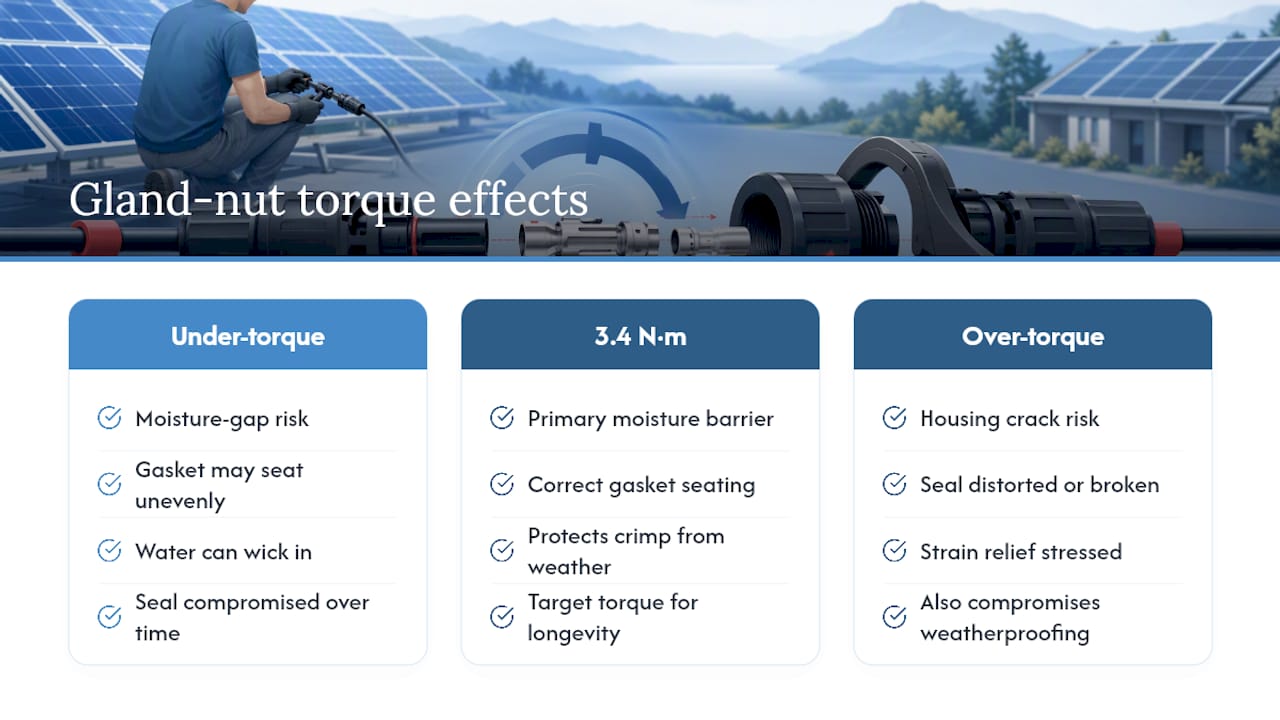
- Torque verification: confirm the gland nut sits at roughly 3.4 N·m using an MC4 torque spanner. Under torque and moisture gets in over time; over torque and you crack the housing.
A visual pass, a tug, a meter reading, and a torque check. Four steps, a couple of minutes, and you’ve caught the majority of field defects a lab would find in far more elaborate testing.
What Are the Most Common MC4 Crimping Mistakes?
Most crimp failures trace back to a short list of repeat offenders.
- Missing gland or cap. If you crimp before sliding these on, cut back the cable, re-strip, and start over. Don’t try to thread a gland over a finished contact.
- Under crimp or over crimp. A loose imprint or a crushed, flared barrel both mean discard the contact and crimp a new one. Never try to re-crimp the same terminal.
- Nicked strands from sloppy stripping. If you see broken or thinned strands, cut back past the damage and re-strip clean.
- Mixing connector brands. Housings and pins from different manufacturers can look interchangeable and still create warranty and compatibility risk. Check brand markings and datasheets before you assume a pin fits.
What Standards and Best Practices Should You Follow?
Two standards anchor everything discussed here. IEC 62852 governs PV connectors generally, and IEC 60352-2 sets the crimp quality and pull-test benchmarks referenced throughout this guide. The National Electrical Code doesn’t spell out MC4 specifics, but its general guidance on torqued terminations applies directly to gland nuts and lugs, which our barn solar wiring code breakdown covers in more depth for outbuilding installs.
Stick with tinned-copper PV wire and same-brand connectors, a point worth repeating because it’s also a corrosion issue, not just a fit issue. Retire or replace crimper dies once they stop producing a clean hex imprint. Most manuals suggest a cycle-based inspection interval rather than waiting for visible failure.
A crimp is only as good as your last calibration check. Dies wear, ratchets loosen, and a tool that crimped perfectly last year can quietly start producing marginal connections. Log your torque checks and label your assemblies. That habit costs you thirty seconds and saves you a troubleshooting session eighteen months from now.
How Do You Weatherproof MC4 Connections for the Long Term?
A perfect crimp still fails if water finds its way in. The gland nut torque you set at 3.4 N·m is your primary UV and moisture barrier. It’s why over torquing (cracking the housing) is just as damaging as under torquing (leaving a gap for water).
MC4 housings are rated for outdoor exposure, but the connectors still degrade faster in certain conditions than manufacturers’ glossy specs suggest. Direct, unshaded, south-facing exposure on a metal roof runs hotter than the ambient temperature most housings get rated for, and repeated thermal cycling stresses the seal over years, not months. If you’re mounting connectors on a barn roof or greenhouse frame that bakes all day, orient them so they’re not sitting in a permanent pool of direct sun if you have any flexibility in the run.
Check that O-rings and gaskets seat evenly with no visible gap before you torque the gland. A gasket that’s pinched on one side and loose on the other will let moisture wick in over a wet season even if the crimp itself is flawless. Route cable so water naturally drips away from the connector body rather than pooling at the housing, and avoid tight bends right at the connector that stress the strain relief.
None of this replaces a good crimp, which is why understanding why solar installation quality affects output is crucial. It protects the good crimp you already made from the environment it has to survive for the next 20 years.
An Installer’s Honest Take on Trusting the Process
The habit that separates a reliable installation from a callback is simple: trust the ratchet, run the pull test every time, and never skip the practice run on scrap cable before touching your real wire. Mark your crimper with the date you bought it. Tools drift out of spec quietly.
— Chris
Fewer Field Crimps, Same Reliable Result
If crimping on a rooftop in July isn’t how you want to spend an afternoon, you’re not wrong to look for another route. Preassembled leads and kit-based systems cut down the number of field terminations you’re relying on for a small project, which means fewer chances for a rushed strip length or an early ratchet release to cause trouble down the line.

Some companies build solar-powered fan kits and off-grid hardware with terminations already handled at the factory, not on your ladder. For barns, greenhouses, and workshops running under 3kW, this can mean less time troubleshooting connections and more time actually using the power you set up. Browse the full Western Harmonics catalog to see kit and preassembled options, or start smaller with the 10W solar fan kit if you’re testing the waters on a single structure. This isn’t a requirement if you’re comfortable crimping your own connections. It’s simply the option for readers who’d rather skip that step entirely.
Sources
- Solarpanelempire
- MC4 connector crimping best practices for solar installers | SurgePV
- MC4 connectors and solar wiring reference | SunForgeLab
- Field-Made MC4 Quick Guide - Energy Library - Tesla